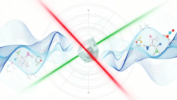
Magnetic optical microscopy is a family of imaging techniques that combine optical microscopy with magnetic sensitivity to visualize magnetic fields, magnetic domains, or magnetic nanoparticles in a sample. Unlike traditional optical microscopy, which relies on light absorption or reflection, these methods detect how magnetic structures alter the polarization, phase, or intensity of light, or how they interact with a magnetic probe. This allows researchers to see magnetic patterns at the microscale or even nanoscale, revealing the hidden magnetic 'landscape' of materials, biological cells, or electronic devices.
History
The magneto-optical Kerr effect was discovered by John Kerr in 1877, but its application to microscopy began in the 1950s with the development of the Kerr microscope. Magnetic force microscopy was introduced in 1987 by Y. Martin and H. K. Wickramasinghe, building on atomic force microscopy technology.
How it works
One common approach uses the magneto-optical Kerr effect: when polarized light reflects off a magnetized surface, its polarization rotates slightly, and the rotation angle depends on the local magnetization direction. By scanning a laser beam across the sample and measuring the polarization change, a map of magnetic domains is built. Another technique, magnetic force microscopy, uses a sharp magnetic tip on a cantilever that feels forces from the sample's magnetic field, with the deflection detected optically. In both cases, the optical readout provides high spatial resolution and sensitivity to magnetic signals.
In practice
Magnetic optical microscopy is used in the semiconductor industry to inspect magnetic storage media, in biology to track magnetic nanoparticles inside cells, and in fundamental physics to study magnetic skyrmions and other exotic spin textures.
Fun fact
Using the Kerr effect, scientists can image magnetic domains in real time while the sample is inside a scanning electron microscope, combining magnetic and topographical information in a single instrument.
Light knocks electrons out of a crystal, and they fly toward the detector like arrows toward a target. From their trajectories, physicists reconstruct how electrons behaved inside the material: with what energy and in which direction they moved. But switch on a magnetic field, and the trajectories bend. The arrows start to curve, the target turns into a warped mirror, and the picture blurs.
A thin section of eucalyptus lies under the microscope objective, and white light, passing through two polarizing filters, turns the wood into a mosaic of purple, yellow, and blue patches. These colors are not random: like letters on a map, they show the direction of the invisible cellulose threads inside the cell walls.
A doctor looks at a screen and sees two images of the same part of the body. One shows where blood is rich in oxygen, the other shows how fast it rushes through the finest vessels. Previously, these images were made by different devices, and combining them was difficult. Now engineers have built a device that takes both images simultaneously.
Electricians working with high voltage are like divers: they need to see what's happening deep underwater without going down themselves. What's needed is a sensor that stays away from the dangerous current and relays information to the surface. Usually, light is used: a beam passes through a transparent crystal, and the electric field slightly rotates it.
An X-ray flash tears through matter in billionths of a second. To remember it, physicists make atoms briefly absorb the light and then release it back. But pulling out a photon on command is like grabbing the right book from a shelf when the shelves move on their own.
The usual approach is to move several absorbers with extreme precision, like a well-coordinated orchestra.
Spectroscopy has always been a way to hear the unheard. Back in the 19th century, Johann Balmer deciphered the elegant lines of hydrogen — a simple numerical harmony that foreshadowed quantum theory.
Deep underground, iron glows white-hot, and the pressure is so intense that an ordinary instrument would be crushed flat. To peer into this world, physicists built a special microscope based on tiny diamond defects (so-called NV centers).
In a small Petri dish sits a droplet of liquid the size of a pinhead. An ordinary scanner wouldn't even notice it: the signal is too weak. But bring a tiny magnetic field sensor close to the droplet, and the picture changes.
Gravitational waves are the trembling of spacetime itself. Usually we only catch their overall hum, but each wave also has a direction of oscillation – polarization. Old maps were built only from signal loudness, which led to errors. It's like trying to see the bottom of a pond through sun glare.
A flashlight beam glides over uneven glass. The glass is massive galaxy clusters, and the flashlight is ancient light born shortly after the big bang. Passing by such clusters, light doesn't just bend around them like water around a rock. Its path shifts slightly sideways, and the amount of shift depends on how the light is 'twisted'—right or left.
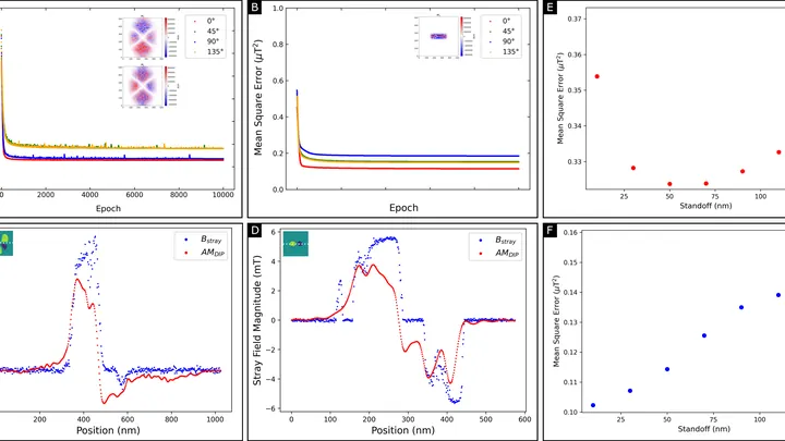
A magnetic film just tens of atoms thick stores information in tiny magnetic vortices. But you can't look inside and see these vortices directly: the instrument only senses the weak magnetic field around the film. Reconstructing the magnetization pattern from such a field is like guessing the shape of an invisible relief from its shadow on a wall.
A surgeon removes a breast tumor, but how do you know no cancer cells are left at the edge? Right now, the tissue goes to a lab, and the answer comes back days later. If the margin is not clean, a second surgery is needed. The new method promises to give the answer right in the operating room, while the patient is still on the table.
An X-ray beam can peer inside an opaque piece of metal and show where cracks or stresses are hiding. But to see such defects, the beam must be focused into a very narrow pencil, just as sunlight is focused by a magnifying glass into a hot spot. In an X-ray microscope, the lens plays the role of the magnifying glass.
A thin film for a solar cell or display is like a dense crowd in a square: each person faces a different direction, and whether light passes through the crowd or gets stuck depends on which way everyone is looking. In organic electronics, molecules play the role of passersby. Until now, instruments could only measure the crowd's overall direction — the average head tilt and its spread.
Biologists often tag cells with glowing molecules — it's like searching for a dim light in the smoke. The light quickly fades, and the smoke creates interference.
An ordinary sheet of paper looks white because it scatters all light rays chaotically. But a butterfly's wing shimmers blue and green without a drop of paint: its surface is covered with microscopic grooves that dampen some light waves and amplify others. Engineers have long dreamed of replicating this trick: creating a material that colors itself simply by trapping light in the right places.
You can make a light beam look like a flower with several petals. If you send such a beam through a cloud of cold rubidium atoms and switch on a magnetic field, the petals start to rotate. The angle of rotation is directly linked to the field's strength.
To avoid losing a fast soccer player in the frame, a drone doesn't need a bright beacon — recognizing the silhouette is enough. Similarly, a neural network now tracks microbes: the algorithm analyzes an ordinary microscope image and instantly finds a bacterium in a drop of water.
Fibers in composites, paper, or biological tissues are often hidden from view, but their orientation determines the strength and properties of the material. Previously, to see fiber directions, you had to take many images at different angles and assemble a three-dimensional picture, like slicing a loaf of bread into thin pieces. For thin samples, this approach doesn't work: you can't slice what isn't thick enough.
A fat droplet inside a living cell is like a bobber in rough water. It doesn't move in a straight line but in jerks, sometimes pausing, sometimes speeding up. Previously, such movements could only be seen in a single plane, like watching the bobber from above without knowing its depth.
A glass marble in a glass of water is nearly invisible, but if you look through it at a checkered tablecloth, the lines behind it appear distorted. Transparent cells behave the same way: light passes through them but is slightly slowed and changes direction.
A tiny needle glides over the surface like a finger over a page written in Braille. That's how a scanning tunneling microscope works: it feels the atomic landscape and turns bumps into a picture. But when you need to add a magnetic field, the design hits a wall.
Light can get stuck inside tiny structures, like sound in a perfectly tuned bell: the energy does not escape, even though there are no walls around. Such states are called 'bound states in the continuum'—light is trapped but not confined in a box. Until now, they were produced in ordinary crystals, where left and right directions are indistinguishable.
A fingernail-sized piece of ceramic is squeezed in a vise, and its internal structure rearranges like clay under your fingers. Inside, orderly rows of tiny domains line up where they were once randomly oriented. After this 'massage,' the crystal lets light through almost like glass and, at the same time, generates a strong electric charge when bent or pressed.
An X-ray image usually brings to mind a bulky machine in a hospital. But such a picture can be taken by a device the size of a palm, assembled from hobbyist electronics. The authors took a Raspberry Pi mini-computer, a 12.3-megapixel camera, and a screen that glows under X-rays.
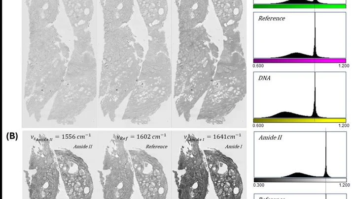
Inside our bodies, between cells, there is a support network — the extracellular matrix. It's like scaffolding made of proteins and carbohydrates that holds cells in place. When the fibers in this network change, it can be a sign of disease — for example, cancer or fibrosis.
Usually, to see these fibers, tissue is cut into thin slices and stained with special dyes.
Terahertz radiation sits between microwaves and infrared light. It passes through clothing, paper, and plastic but is blocked by water and metal. That's why these waves are used in security scanners and for quality control of materials.
A magnetic field is invisible, but you can make it 'glow' using tiny defects in diamond — nitrogen-vacancy centers. Each such defect acts as a miniature compass, telling you which way the field points. The problem is that there are many of these compasses, and reading them all in sequence is like transcribing every letter in a thick book by hand.
A typical 3D printer squeezes out plastic like a pastry chef piping cream from a bag. Here, instead of plastic, it's light. A laser beam draws in liquid resin, making it solidify at precise points. This creates parts too small to see without a microscope.
Until now, such printers were slow: the beam crawled across the surface like a pen on paper.
In the mud at the bottom of a pond live bacteria that carry tiny magnetic compass needles inside them. These needles are chains of magnetite crystals that help the bacteria swim along Earth's magnetic field, like a compass needle, in search of better conditions.
A pathologist looks through the eyepiece and sees a pink-purple tissue section — the classic hematoxylin and eosin stain. The dyes bind to nuclei and cytoplasm, and the color tells the doctor about the disease. But preparing the slide itself takes hours: fixation, paraffin embedding, sectioning, staining.
This new device skips the dye.
A magnetic field is invisible, but you can make it 'glow'. To do that, take a tiny diamond with defects — places where a carbon atom is replaced by nitrogen and a neighboring lattice site is vacant. These defects, like sensitive compass needles, respond to the slightest changes in the magnetic field and emit light of varying brightness.
An ordinary magnetic compass freezes when lightning strikes nearby. A sudden jump in the magnetic field throws the needle off. A similar problem has been hindering scientists trying to measure magnetism in strong pulsed fields: those that switch on for a thousandth of a second.
The new setup tackles this with a laser beam.
Light from distant galaxies passes through telescope lenses like through a stack of window panes. Each pane is coated with a thin film to reduce glare. But this film acts as a polarizing filter: one component of the light wave passes a bit more freely, the other a bit worse. As a result, the wave rotates slightly, and the telescope sees a different picture than what is in the sky.
A cell doesn't just lie on a surface: it probes it, pulls it, and pushes it. Until now, instruments could only detect direct forces: how hard a cell presses or stretches its support. But if you grab a cell by the "shoulders" and give it a slight twist, it responds by rotating, and until recently, no one could measure that rotation.
A camera that sees ultraviolet light typically costs as much as a nice car. That's because it requires a special crystal and a complex fabrication facility. Engineers in Korea took a different approach: they grabbed a run-of-the-mill chip, the kind made by the millions for phones, and sprayed a thin layer of metal-oxide nanoparticles onto it, like paint from a can.
Entangled photons are like twins: what affects one instantly affects the other, even if they are separated by kilometers. Until recently, observing such a connection required detectors that counted each photon individually in pitch darkness. Physicists simplified the task by swapping them out for a regular scientific camera.
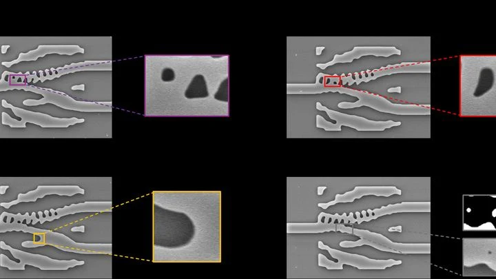
Modern computer algorithms design photonic integrated circuits — light chips capable of separating signals by frequency (color) for spectroscopy. Unlike traditional engineering, light paths in these chips are not straight waveguides but chaotic, almost organic mazes.
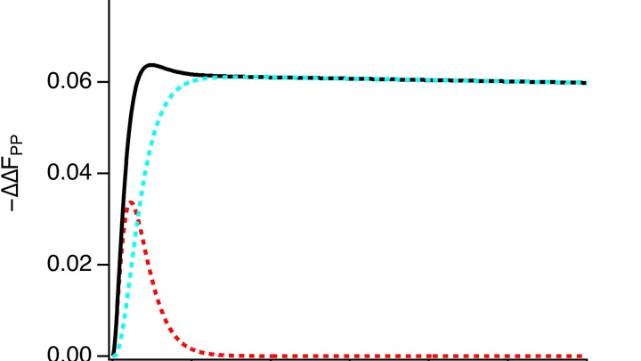
Inside every living cell, chemical transformations are constantly taking place. Some of them create unstable particles whose electrons behave like paired magnets. Their interaction resembles a dance: each movement of the pair responds to external magnetic fields, as if to a changing rhythm.
Two pendulums linked by a spring of light begin to swing in unison without ever touching. In the quantum world, such synchronization means something more: particles lose their individuality and become a single object.